NONIK0 Project Writeup
Introduction
After getting my first working Rust "tech demo" animation running on Light Rail, I found myself wanting to dive deeper into embedded Rust development while also just wanting a mental break from working on my earlier Light Rail project. I decided that I would work on another more simple project and continue experimenting and learning Rust while doing so. The idea for this project came together fairly quickly because several factors aligned at once. First, I had been itching to try out these little retro dot matrix displays (HCMS-29XX) in my next project. I had originally discovered them while looking around for Light Rail components. Second, I wanted to design an even lower power battery device compared to Light Rail, where it could run off a single CR2032. The ACK1 hardware was a big design inspiration here as a minimalist design reference. Finally, I wanted to try OSHpark's AfterDark service. The matte look and the color scheme of the PCBs really appealed to me, so I wanted to try to use it as part of my design.
Hardware Design
Prototype and Concept
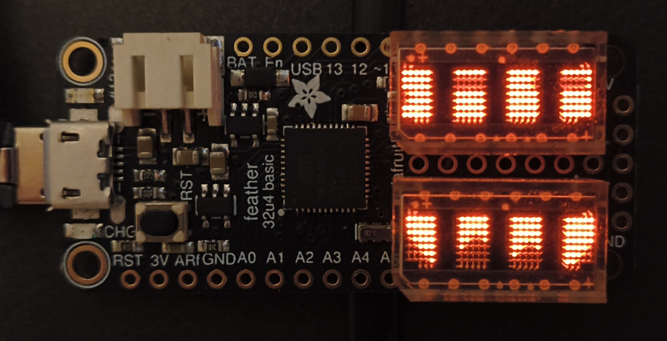
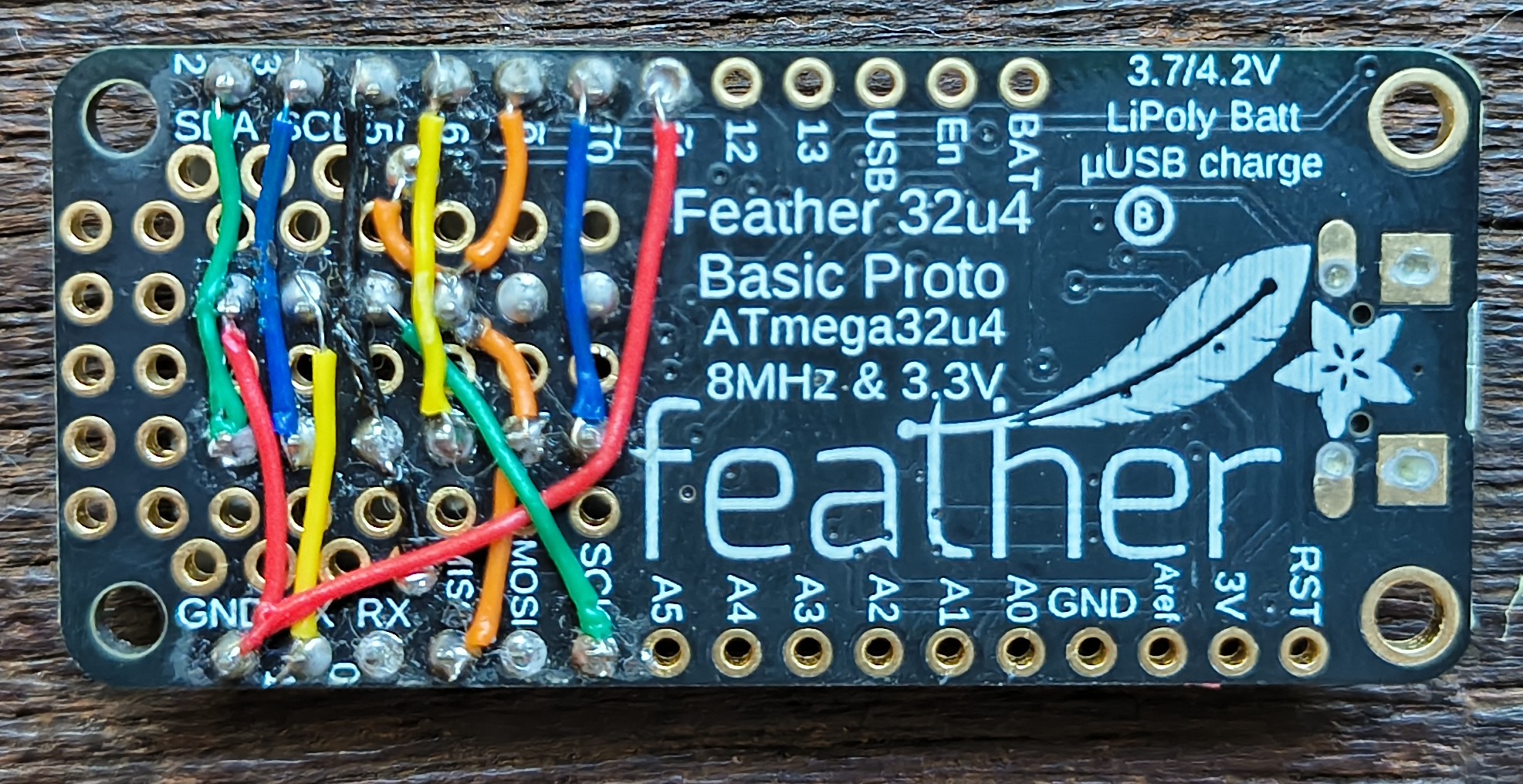
Before I had started in earnest with this project, I had made a simple prototype using an Adafruit Feather 32u4 Proto and two 4-char HCMS-29XX displays. It was helpful for a reasonable approximation of what I was envisioning in my head, which was to design a small wearable battery-powered device to showcase the dot matrix display (and then learn some more Rust). I decided early on to base the design around ATtiny1604. I selected the ATtiny1604 because it had the right number of pins for what I needed and it supported UPDI programming (1 pin programming! 3 with power and ground). For the PCB layout, I wanted to embrace the visible trace aspect of the AfterDark finish by using thick traces arranged in a maze-like motif, using right angles and rigid spacing throughout.
PCB Layout
When I began layout, I first wanted to establish the overall dimensions of the PCB. I started from the Adafruit Feather spec size, whose height roughly matches the footprint of a standard CR2032 battery holder, including the solder contacts. However, rather than orienting the battery holder this way on my board, I rotated it 90°, which let me shrink the PCB height to just a small margin over the width of a CR2032 (32mm). I also extended the length of the PCB a bit so I could fit a second battery holder on the back, which could hold either a spare battery or a magnet (so the device could be attached clothing with another magnet, or to a ferromagnetic surface).
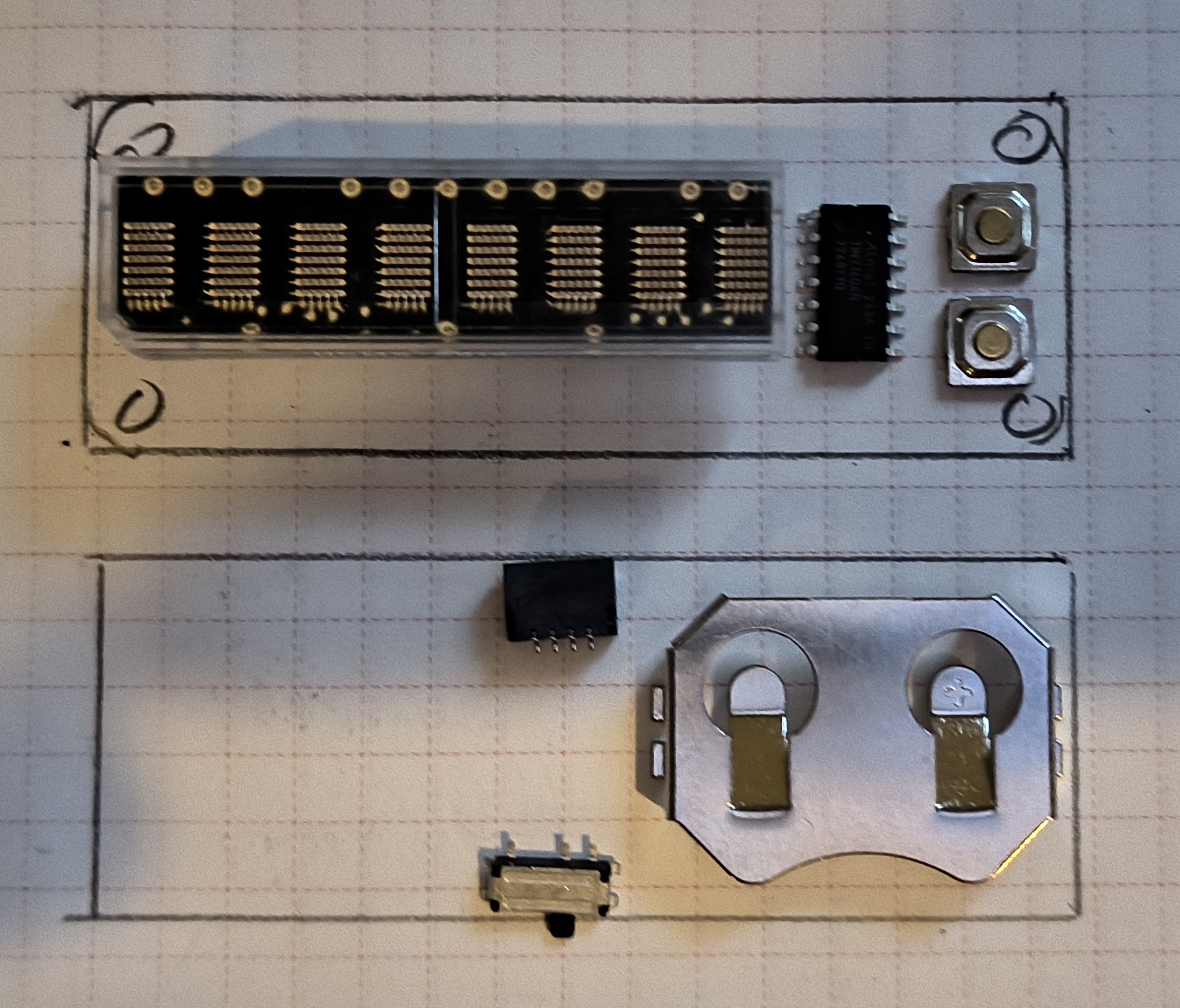
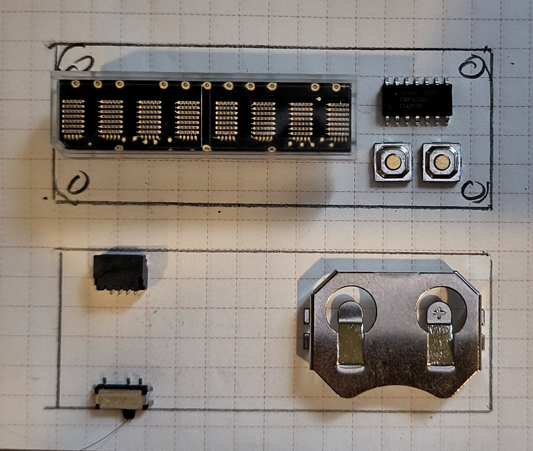
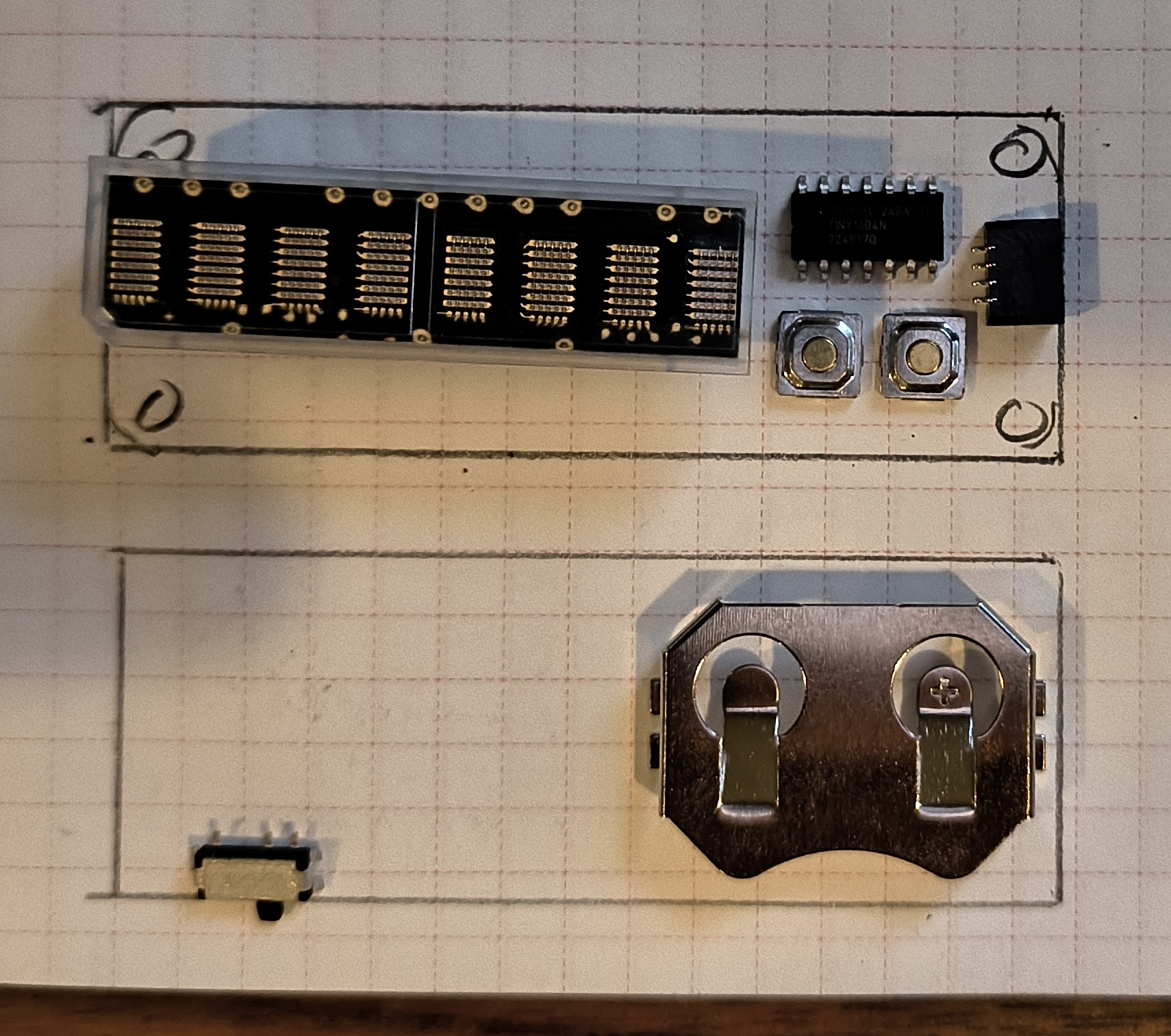
With the board dimensions set, I drew them up on a sketch pad and came up with a layout I liked after a few minutes. The dot matrix display was centered and to the left of the ATtiny and two buttons. I found a tiny little 2mm buzzer that was able to fit in nicely just above the display. I placed a small LED below the display and connected to the display's data out pin to function as display update indicator. On the back of the board, in addition to the two battery holders, I added a power switch, a JST-SH 4 pin connector, and the UPDI contacts. Then, I laid out the traces in accordance with the maze-like aesthetic I had in mind—thick, visible traces that used only right angles, meandering a bit to fill the available space on the board. I also added test points on the front to help with this as well. Towards the end, I decided (and managed) to cram in some additional circuitry in between the two battery holders on the back. If included when assembled, it would give the option of boosting the LED supply voltage to 5V. This would let me test the displays with different LED supply voltages (technically the HCMS-29XX datasheet states a required 5V for the LEDs but in my usage/testing up to that point seemed fine at ~3.3V). Then, I ordered the boards from OSHPark.
Hardware Testing
After a few weeks I got the boards, and I was eager to test them with some test C++ code before I started with Rust support. After assembling one with my mini hot plate, I was very happy when I was able to clip my UPDI programmer to the board and flash the ATtiny within minutes. However, after the successful flashing, nothing happened. For a bit I had some initial befuddlement wondering how flashing was working flawlessly any code I uploaded was not. I channeled my inner AVR guru and the word "fuses" materialized in my mind. After a quick lookup, I was able to update the PlatformIO configuration to write the proper fuse settings when flashing (and the fuse settings are automatically determined, nice!). Then after another flash and seeing the fuses written in the shell output, I then looked down on my desk to see a beautiful, orange-hued message shining on the HCMS display—" test "! I then took a breath for the first time since I initially flashed the hardware.
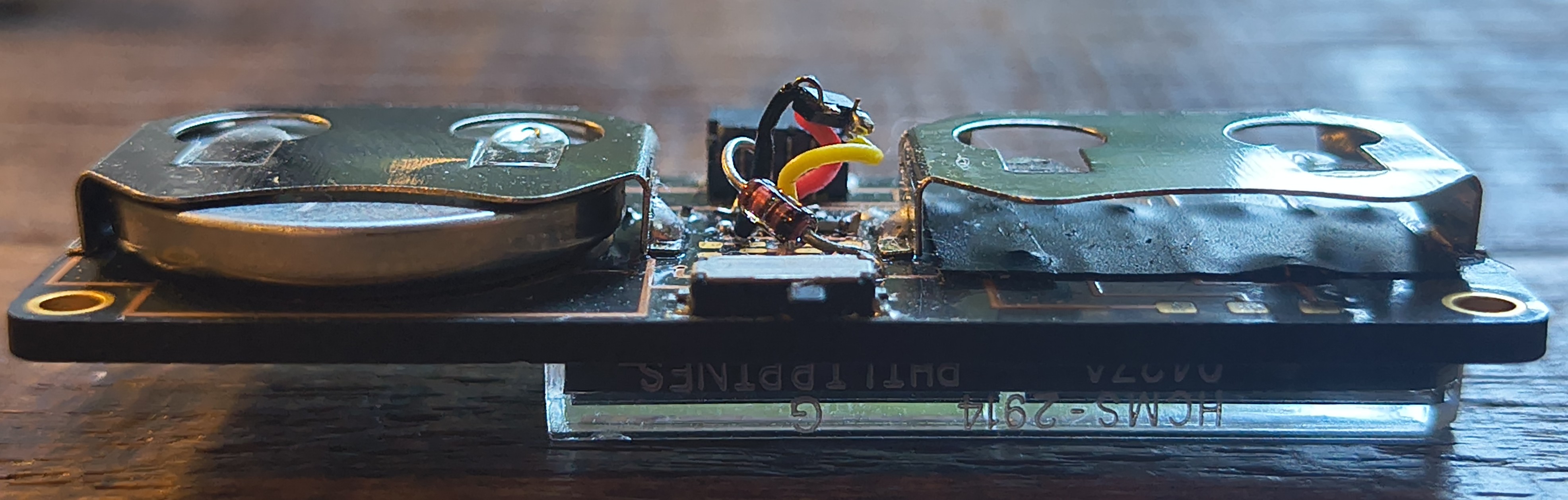
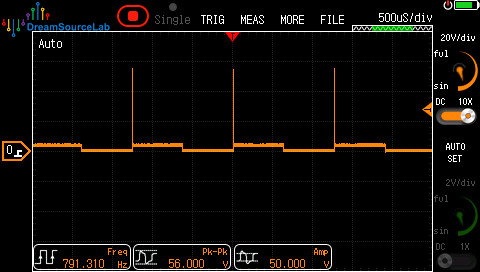
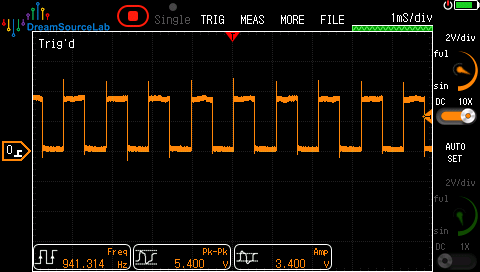
With the biggest mental hurdle out of the way (a functional board), I moved onto testing the hardware. Testing with and without the optional 5V boost circuit showed it wasn't worth including—no meaningful brightness improvement, an audible switching noise, and the ATtiny browned out on CR2032 batteries. In fact, I was able to get a decent brightness from the display using some "dead" CR2032s. The buzzer was audible but quiet, and dropping the resistor to drive it directly from a pin made it slightly less so. I also jury-rigged a driver circuit with a transistor on the back of the board to (properly) drive the buzzer, and with that addition the buzzer volume was much more audible. I was curious if I would need the usual flyback diode for the inductive kickback for such a small little buzzer. Given that I recently acquired a decent oscilloscope, I was happy to mess around and find out. I was surprised to see that the kickback from the buzzer on the collector when the transistor closed was over 50V! With the diode in place, the spike was reduced to only a couple volts, so a 25x reduction! Keeping the diode.
Rust Support and Firmware
With the hardware validated, I could start digging into the Rusty firmware stuff. However, getting any Rust to run on the ATtiny1604 required laying some ground work first. The most popular Rust framework for AVR microcontrollers, avr-hal and avr-device, did not yet support the ATtiny1604. Then once this support was in place and supported the required hardware peripherals for this project. I would need a Rust driver for the HCMS-29XX display, as well as other primitives I will get into.
Basic Rust Support
Adding the "Rust support" to the ATtiny1604 came in a couple steps. First, I added support to avr-device for the ATtiny1604, along with the rest of the ATtiny X04 family. The avr-device crate is essentially a wrapper for svd2rust, which generates the register access abstractions for supported AVR chips using svd files. There's actually not much interesting to say about this step. I just followed the README instructions in the repo and looked at work from similar PRs. I had to grab some metadata files from Microchip and update various includes and metadata type stuff. The second step for Rust support was adding support in avr-hal, which is the crate that provides the Arduino-like abstractions for AVR chips. The most noteworthy aspect of updating avr-hal was that all of the currently supported chips with avr-hal are based on two AVR architectures—tinyAVR and megaAVR. However, the ATtiny1604 is based on the newer XMEGA AVR architecture. This meant a whole additional crate would need to be added to be able to support the ATtiny1604 or any other XMEGA chip. Luckily, after digging into PRs in the avr-hal repo, I found a two-year old, incomplete PR that already had a lot of the work to add basic support for ATtiny404 with basic GPIO. With a rebase to the current state of the avr-hal repo and a few necessary tweaks and adding support for the rest of ATtiny X04 family, I was able to get a simple test project building that was targetting ATtiny1604 using my dispaly driver. Then I used avrdude to upload the compiled binary file and...it worked right out of the gate! This sort of thing feels like a lottery ticket when working with C++. Another testament to the Rust compiler and its runtime assurances.
Basic Peripheral Support
With the basic Rust support out the of way, I started working on cleaning up some more of the core functionality I would need. Porting over my tone and random implementation from Light Rail went fairly smooth. The tone implementation required more changes to get working considering the differences the megaAVR and XMEGA architectures and how the timers and interrupts are managed. I referenced the tone implementation in SpencerKonde's MegaTinyCore for some changes. I also used the EEPROM implementation as a reference as well and was able to add it cleanly to the existing shared EEPROM traits in avr-hal. The implementation uses inline AVR assembly and is similar to the assembly code in MegaTinyCore with a few adjustments to the registers used. This was my first time using inline assembly in Rust and I found it to be relatively painless. What was painful, however, was attempting to get the EEPROM implementation to work without the inline assembly and instead using avr-device's register access. I tried a lot of different things to try to get the EEPROM to successfully write any data. The datasheet clearly says that specific instructions need to be done within 4 clock cycles of each other to work, so I am just assuming that the compiled code is bloat somewhere and the critical timing is not being met. It would explain why the MegaTinyCore implementation was in assembly. Decompiling the bin to investigate the assembly and pinpoint the issue is something I'd like to do in the future, but with the working assembly implementation I could wrap up and move on.
Control Flow Design
With all the aforementioned Rust prereqs out of the way, I started on the core firmware logic. Thanks to my earlier reviews of other Rust project writeups and source code, I had a good idea of how I envisioned the core loop would operate. From a feature-standpoint, I wanted to be able to configure and show a name, adjust the display's settings, and also show an animation. I would encapsulate these features into several named modes with a simple menu interface to navigate and change the currently active mode. So the control flow would be structurally simple: have a main loop that each cycle will process input events, process them within the context of the main loop, then call an update function for the active mode. Each mode would implement this function and be able to handle its own specific logic, with passed references for shared access to state and peripherals. In Rust pseudocode that roughly looks like:
loop {
    // process input events, if any (e.g. button press/hold/release)
    let event = process_input()

    // process event in "shared" context (e.g. handle tone for button presses, switching modes)
    mode = process_event(&event)

    // call update for active mode mode, passing event, state, and peripherals
    mode.update(&event, &state, &peripherals)
}
This approach is deliberately simple and barebones — we're a far cry from having access to fancier embedded async frameworks like embassy, just a single main loop. So every cycle of the main loop, the input would be processed and potentially emit an event (e.g. enum with discriminants like LeftButtonPressed and RightButtonReleased). Then, the current mode would have its specific update function called, passing the event, if any, along with a shared state and peripherals struct by reference. This pattern of passing around references works really well with Rust's borrow checker. The display object, as part of a shared peripherals struct, gets passed to the active mode and can be used to update the display, and the mode never takes ownership of the display object. In Rust, this is very clean approach relative to other options for sharing access to a hardware peripheral or shared state that would be fairly common in other languages, like using a static/global variable. So many design patterns that would be relatively simple in C++, like the static global variable, in Rust become a struggle with the compiler. By design Rust makes certain classes of traditional bugs, like data races with mutable statics in this case specifically, into compile time errors. So if you are attempting an "unsafe" pattern in Rust and going against the grain, the compiler will let you know. With the mutable static case in Rust, you'll need use a sync primitive or two (or judicious use of unsafe itself). Even with simple chips like the ATtiny1604, data races with a "single" core/thread/loop are possible because of interrupts. This is how the tones are generated and play asyncronously with the code. My tone implementation makes use of sync primitives for safe shared access of the tone state between the interrupt handler and the main loop. What I have learned is that if I'm struggling or working a bit extra to get a design pattern to work (i.e. compile) in Rust, it's probably for a good reason. Rust pushes you toward patterns that are generally much less prone to specific classes bugs that can be caught before runtime, specifically enabled through the design of the language itself. I like it. That's a very different experience from C/C++ land, where you can throw cast data however you please and pass around pointers to anywhere fairly willy-nilly.
Dynamic Dispatch
Once I had the general control flow in mind, I needed to figure out how to actually implement the modes. In most languages/environments, this would be straightforward - you'd define an interface that all modes implement, then store a reference to whichever mode is currently active, dereference and call interface. There is corresponding concept to interfaces in Rust with trait objects. However, we are not in a standard environment, we are in no_std. That means there is no stack overflow protection (foreshadowing!) nor a heap for dynamic memory. Objects that would normally live on the heap need static or stack-allocated alternatives instead. C++ has been around a while so there's plenty of options available for working in heapless environments but Rust is still fairly nascent in embedded so both the options of libraries (crates) as well as shared developer knowledge from places like SO and articles is much thinner (and consequently the amount of training data for LLMs). I searched and LLM-prompted for heapless trait object and got a link/reference to this stackoverflow question from both, so I just went with it.
As the SO question mentions, using references instead of Box types (heap-allocated) adds lifetimes and additional complexity. Our friend the borrow checker needs to ensure that the lifetime of the references will outlive the objects that own them. Using a Mode trait to define the signature for the update fucntion, my initial solution ended up using an array of static mutable references for Mode trait objects with static lifetimes, or as Rust:
[&'static mut dyn Mode; NUM_MODES]
It honestly took me a lot of trial and error and asking AI tools with help to better understand lifetimes before I got some traction with the compiler and the number of errors started going down with each change I made. Writing this, I definitely have a better handle on lifetimes now and I have learned that when using them they tend to spread through Rust code like a virus, infecting everything they interact with. If you find yourself using them extensively, you should be able to articulate why - otherwise it usually means you haven't explored simpler design patterns enough. At the time I was happy enough with my reason, the modes themselves were statically allocated, and so they maintained their state in between mode switches. However, as I implemented more modes, this approach became problematic due to memory constraints - which I'll cover next. As for the modes themselves, implementing them was mostly straightforward without much to comment on, you can refer to the documentation for more details on them.
Dealing with Constraints
The static array approach I described worked initially, but as I implemented more modes (as I fell prey to scope creep) and started consuming more resources on the chip, I started hitting the ATtiny1604's memory constraints in unexpected ways. While I was pretty happy when I was able to get a custom panic routine working early on in development, where I could output debug panic data on the display, I was disappointed when I found myself running out of flash soon after and I couldn't compile all the modes I was working on. Using cargo-bloat, I was able to see how the panic handler was using ~6KB out of the total 16KB of flash! I opted to initially work around this constraint to focus on finishin the modes by adding Rust features. Then I could conditionally compile out the panic handler and specific modes as needed. I also found other optimizations such as strategically avoiding use of specific functions in crates like heapless to further reduce the flash size by several KB.
However, as I was wrapping up the last few modes, I started to see signs of memory corruption when testing the firmware where it would become unresponsive and/or the display would output garbage. At first, because I had just been working on changes for reducing the flash usage, I assumed the issue was a bug in my recent updates. I had been shifting from using large match statements for display output to indexing into const arrays for string data. I thought that since I had experimenting compiler settings and building in release to save space in the flash, that could be the culprit. However, after some investigation, that turned out not to be the case. The biggest clue was the "heisenbug" nature of the problem. When I removed modes to make room for the panic handler, the memory corruption disappeared. But as soon as I added the modes back, the corruption returned. The act of trying to debug the issue was actually fixing it.
Given the heisenbug behavior, I then was able to turn my attention to a different constraint entirely—SRAM. The ATtiny1604 has only 1KB of SRAM, and since my dispatch solution was holding all mode data statically, that was probably cutting directly into the stack size. Using the avr-size profiling tool, I took a look at the size of my firmware's memory segments:
   text    data     bss     dec     hex filename
  16057     298     351   16706    4142 target\..\NONIK0.elf
The baseline/at boot SRAM usage was 298+351=649 bytes, which left only 1024-649=375 bytes for the entire stack. I had a pretty good smoking gun at this point.
An Improved Dynamic Dispatch
With the SRAM issue diagnosed, I knew needed a different approach but didn't immediately tackle it. Instead, I was able to get the firmware to a stable point without too much refactoring by simply compiling out one of the modes that used more SRAM. Around this time, I took a break from this project to pivot back to Light Rail. However, it wasn't long before I had to revisit the same dynamic dispatch problem in Light Rail for its different gameplay modes. I instinctively recoiled at the notion of just reusing the static array dispatch since I already knew the con of increased SRAM usage was pretty bad on a chip already constrained by SRAM and I also just wanted to keep trying different things.
So the solution I discovered in Light Rail, and immediately ported back to NONIK0, is called enum dispatch. With enum dispatch, the mode trait objects are wrapped within the discriminants of an enum (a neat Rust feature). What this improves over trait objects being held in a static array is that now there is just a single instance of the enum for the currently active mode held in SRAM, not all of them! The actual size allocated in memory will be the size of the largest enum discriminant with some overhead. There were some initial hiccups when the flash size ballooned after intially implementing this approach. After taking a look at the binary with cargo-bloat, I saw how the dispatched update() functions were being duplicated in the flash by the compiler, which was unfortunate give these were large functions. A light application of #[inline(never)] on the dispatch functions fixed the bloat instantly. With a working build using the new approach, I used avr-size once again to profile the memory segments:
   text    data     bss     dec     hex filename
  15669     234      19   15922    3e32 target\..\NONIK0.elf
Wow. The new baseline SRAM usage was now 234+19=253 bytes, down from 649 bytes. With only 1KB SRAM total, that made a massive difference. Manual testing confirmed that all was well and I was not able to repro the memory issue again. While I did like how the array approach kept each mode's state intact between switches, clearly given the constraints present, enum dispatch was definitely the better solution to go with. I later found the enum_dispatch crate that allowed me to remove the boilerplate dispatch function and have it be generated by the crate! And with that, I felt a reasonable degree of project completion.
Conclusion and Next Steps
Overall, this project was a great success for me. I had fun doing it, as evidenced by all the unplanned modes I implemented (especially tinkering around with the ADC). But beyond that, I was able to take a break from Light Rail and continue to become more adept using Rust without simultaneously overburdening myself with thinking up gameplay ideas and such for Light Rail and struggling to implement them. I gained a lot more confidence working with Rust at a low level and it's a unique feeling to know I was one of the first people to run any Rust code on this family of AVR chips! Having to deal with the memory constraints of the chip were frustrating at first but ultimately very valuable. The constraints forced me to explore outside the "easy mode" alternatives that exist in std Rust and instead pushed me to seek and try out more design patterns that I wouldn't have discovered otherwise. On top of the valuable Rust experience, I now have a functional, wearable, battery-powered, fancy LED display nametag to finish out my vision from the beginning.
Having achieved the core project goals, there are a couple more things I'm looking forward to as a continuation of this project. One is contributing some of my work back to the Rust open-source community through more PRs like my latest in avr-device. I also already have a new PCB revision ordered that fixes the I2C pin assignments for the JST connector and includes the buzzer driver circuit I managed to cram onto the back. I'm looking forward to adding I2C functionality and eventually implementing an I2C scanner/tester mode.